Logic gates
Numéro d’image : 11894066
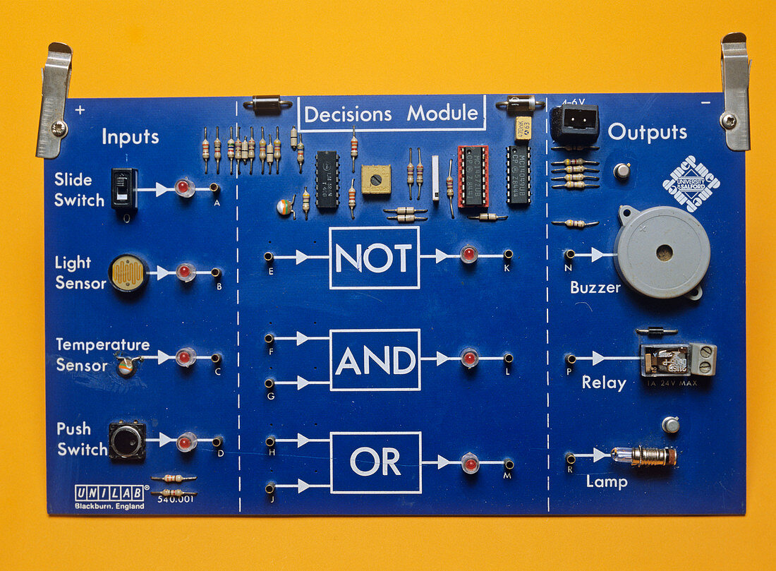
| Logic gates. Circuit board designed for testing logic gates. A set of inputs,comprising switches,a light dependent resistor and a thermistor connect via logic gates to a set of outputs. These can be wired so as to produce different set-ups. A NOT gate has one input. It will output the opposite of this (so on goes to off and vice versa). An AND gate outputs if and only if both its inputs are on. An OR gate outputs if one or more of its inputs are on | |
| Licence : | Droits gérés |
| Crédit: | Science Photo Library / Andrew Lambert Photography |
| Taille de l’image : | 4877 px × 3586 px |
| Model Release : | Non requis |
| Property Release : | Non requis |
| Restrictions : | - |
Prix pour cette image À partir de 45 €
Produit vendu
(Calendrier, Carte postale, Carte de vœux, Impression sur textile, Packaging etc)
À partir de 45 €
Usage commercial
(Affichage, Annonce presse, Annonce TV, Carte, Digital - hors rés. sociaux, Digital - rés. sociaux etc)
À partir de 45 €
Éditorial
(Digital, Journal, Livre, Livre pratique, Magazine, Télévision etc)
À partir de 60 €
Usage non-commercial
(Digital - hors rés. sociaux, Digital - rés. sociaux etc)
À partir de 120 €
Mots clés
- aide pédagogique,
- appareil,
- apport,
- capteur,
- capteurs,
- circuit,
- commutateur,
- contribution,
- décision,
- décisions,
- dispositif,
- électronique,
- entrée,
- équipement technologique,
- et,
- interrupteurs,
- lampe,
- léger,
- non intégré,
- ou,
- pas,
- portes,
- relais,
- résistance dépendante lumière,
- résistances,
- résistances dépendantes de la lumière,
- résistances dépendantes luminosité,
- résistant,
- senseur,
- sensible,
- sortie,
- système,
- technologie,
- technologique,
- température